
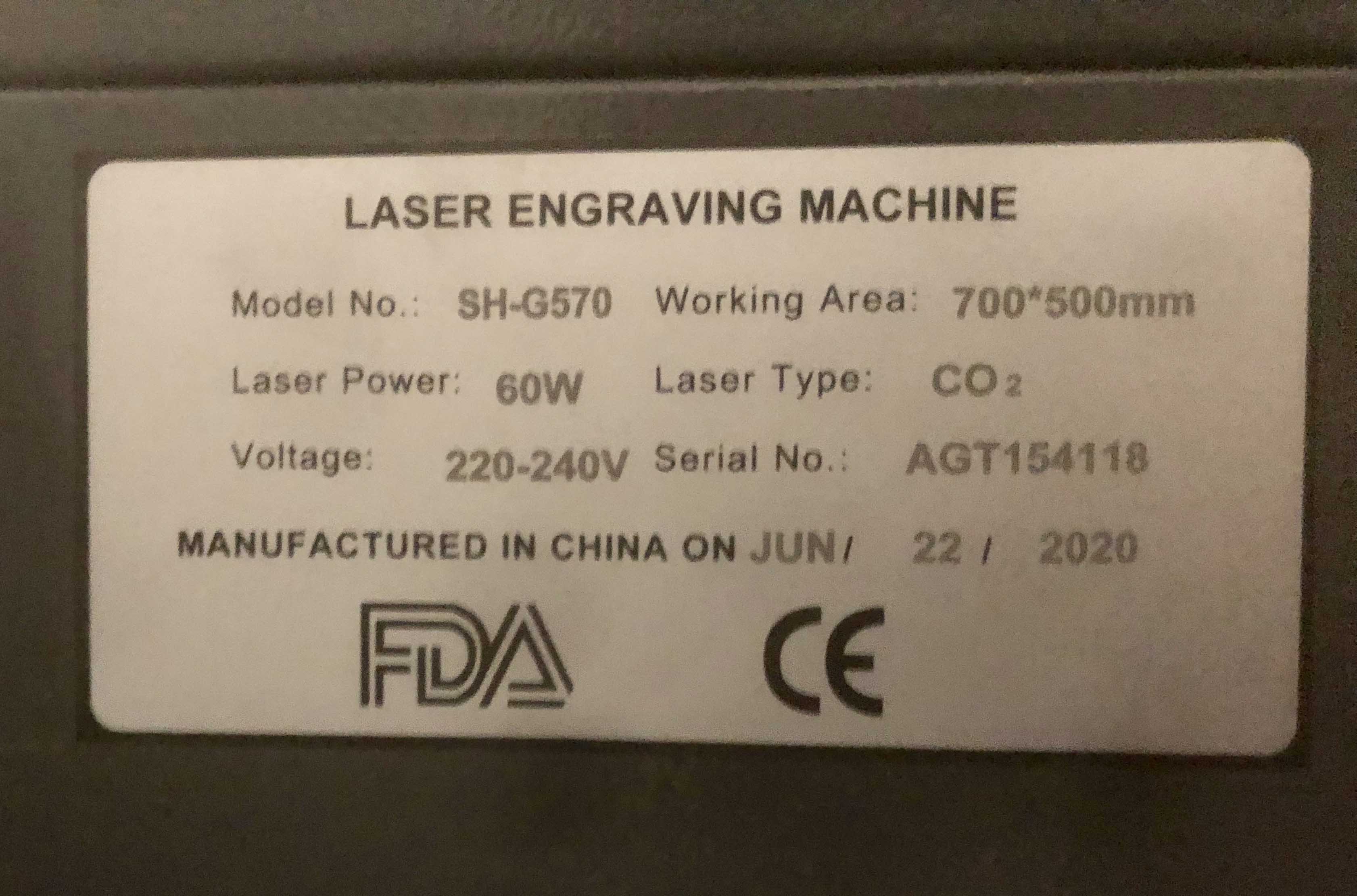
Hello all, new to the forum and new to the world of lasers so really hoping someone can help me. Recently purchased a second hand laser, spec plate attached as image. Saw it running so all seemed ok. it didn’t have a CW3000 chiller just the pump in a bucket of water set up. I managed to purchase a chiller at a good price but needed a repair which has now been done. As far as I can tell it is working apart from the fact when you turn it on sometimes it alarms but with a squeeze of the tube it seems to correct itself, doesn’t happen every time.
When I first set it up and connected it to the chiller straight away the water filled up the laser tube and you could see water in there. Apart from a few air bubbles which I eventually got rid of all was fine.
I then started some samples to get best speed and power settings with my son, all very exciting.
Then for no reason we can fathom the water has stopped circulating and indeed no water in the tube. I have disconnected it and checked the lines as best I can for kinks and blockages and checked the chiller that it is pumping but can’t get water to the tube.
Any advice on this would be very helpful and thanks in advance.
Does the setup include a flow sensor. This will look like a small plastic barrel with a hose connectors either side and wires coming off, usually wired in before the water inlet on the anode (high voltage) end of a laser tube.
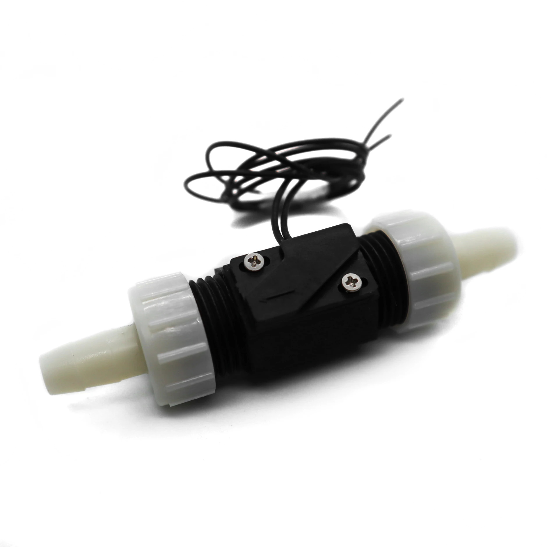
They usually look like this (above, often on your model of machine they are white). If I had to make a bet on the issue from the information you’ve given, I’d bet you’re trying to run water the either the wrong way through a flow sensor. Though it doesn’t matter which way the water flows through the tube (in principle) it should not flow the wrong way through the sensor. They often have a flow direction arrow on them and can be semi-dismantled to check for crap blocking them. As they use the flow of water to move a magnet (usually their design can vary) to open a switch the flow needs to be in the correct direction.
Their job is to prevent the power supply or the controller from allowing the laser to fire if water isn’t running properly, but they can easily be stuck in the “On” position or over-ridden in software or firmware settings or simply disconnected or shorted to the PSU, this is all depending on the setup of the machine which varies wildly from model to model, make to make and so on.
If you still have the water pump and plastic box (nothing stopping you just using a very large amount of water) then I’d be tempted to try testing the setup with that, as with that setup you can easily check if water is flowing through the tube.
Photos of the tube and your general setup would be helpful.
Hello Smokey. Thank you very much for your quick reply and very informative answer. Tbh I never expected that on a forum so this is very much appreciated.
At first I thought you were referring to a flow sensor possibly in the chiller but it appears not. Bizarrely I meant to add this part last night but didn’t have the photo at the time but hopefully you can see form my photo attached some of the laser tube and what possibly appears to be the flow sensor.
When the laser started to malfunction I opened up the inspection hatches around the laser and noticed water dripping through this area and pulses of light probably from the laser. This is when we shut it down as clearly this wasn’t right and water mixing with electrics is never a good combination and was quite scary. It looks as though this will unscrew and hopefully I can have a look and see if anything is wrong with it. I’ll not take it any further until you can confirm this is the flow sensor. Can you confirm that the set up I have from my chiller to the laser is chiller/outlet to laser/inlet. Thanks.
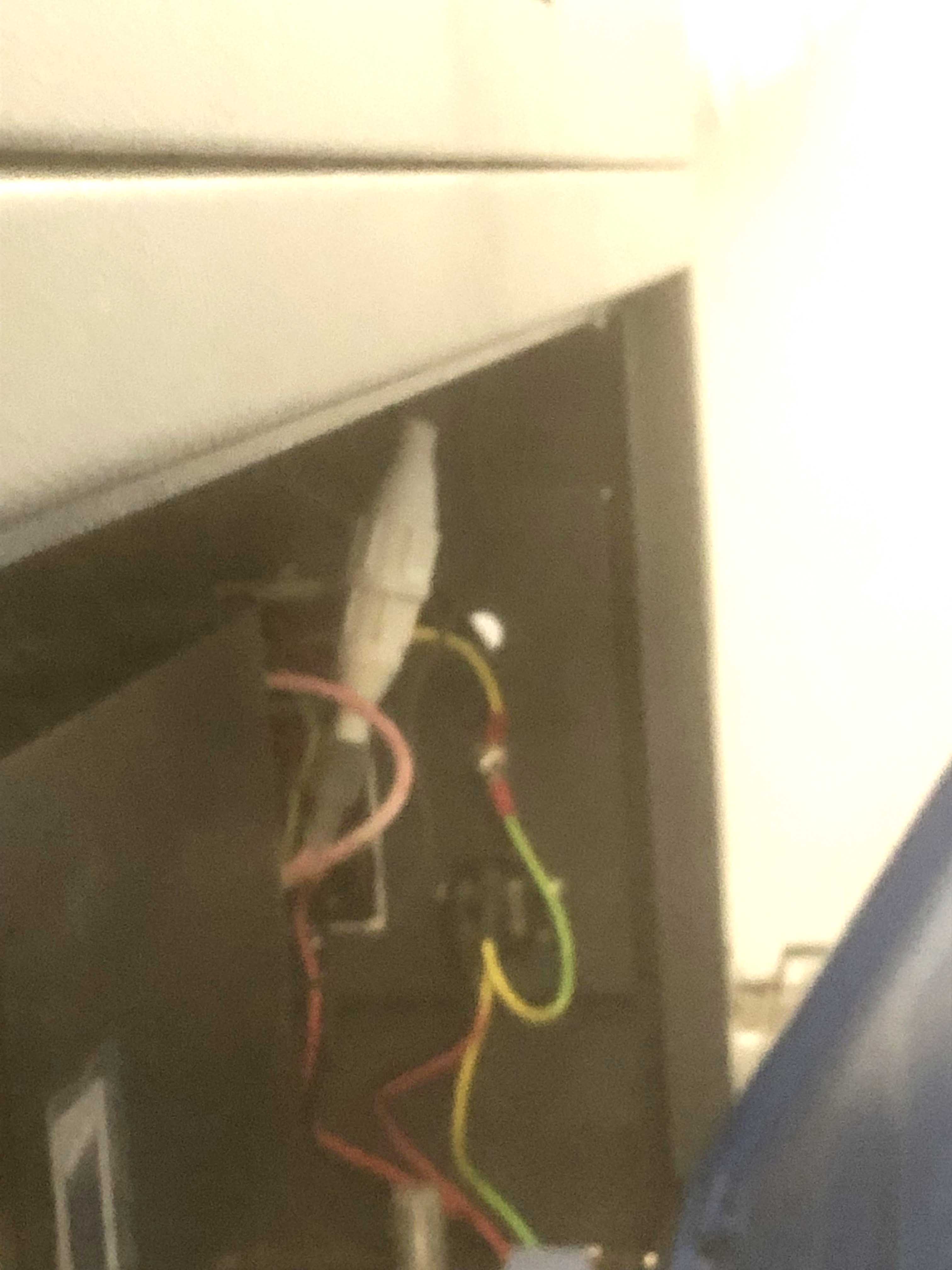
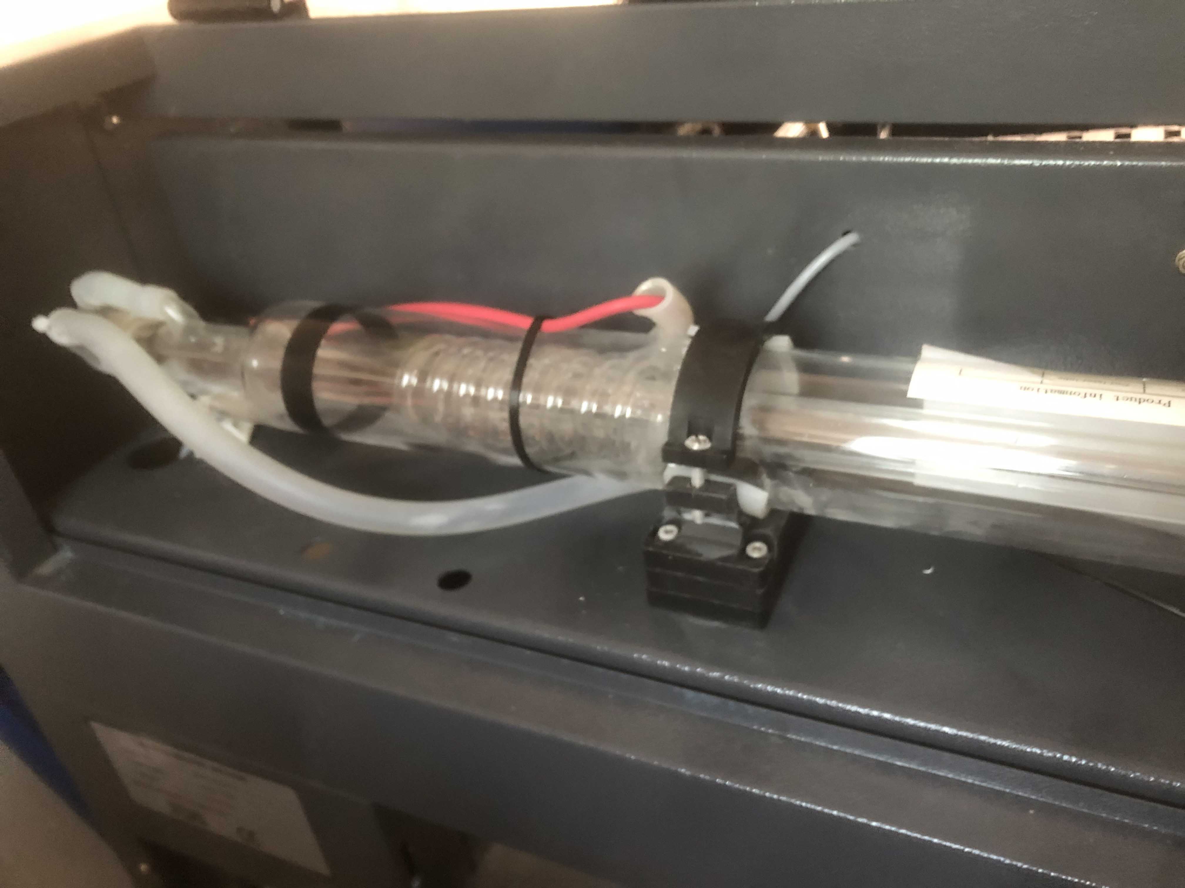
The item in your first photo is a high voltage connector, where the high voltage that is needed to make your tube strike connects to the tube via that red wire and is nothing at all to do with water flow… in fact this needs to stay well away from water.
The photos are too blurry/very poor quality so I can’t see whats going on in your tube but it looks normal enough given the photo quality, as far as I can tell the correct bit is filled with water.
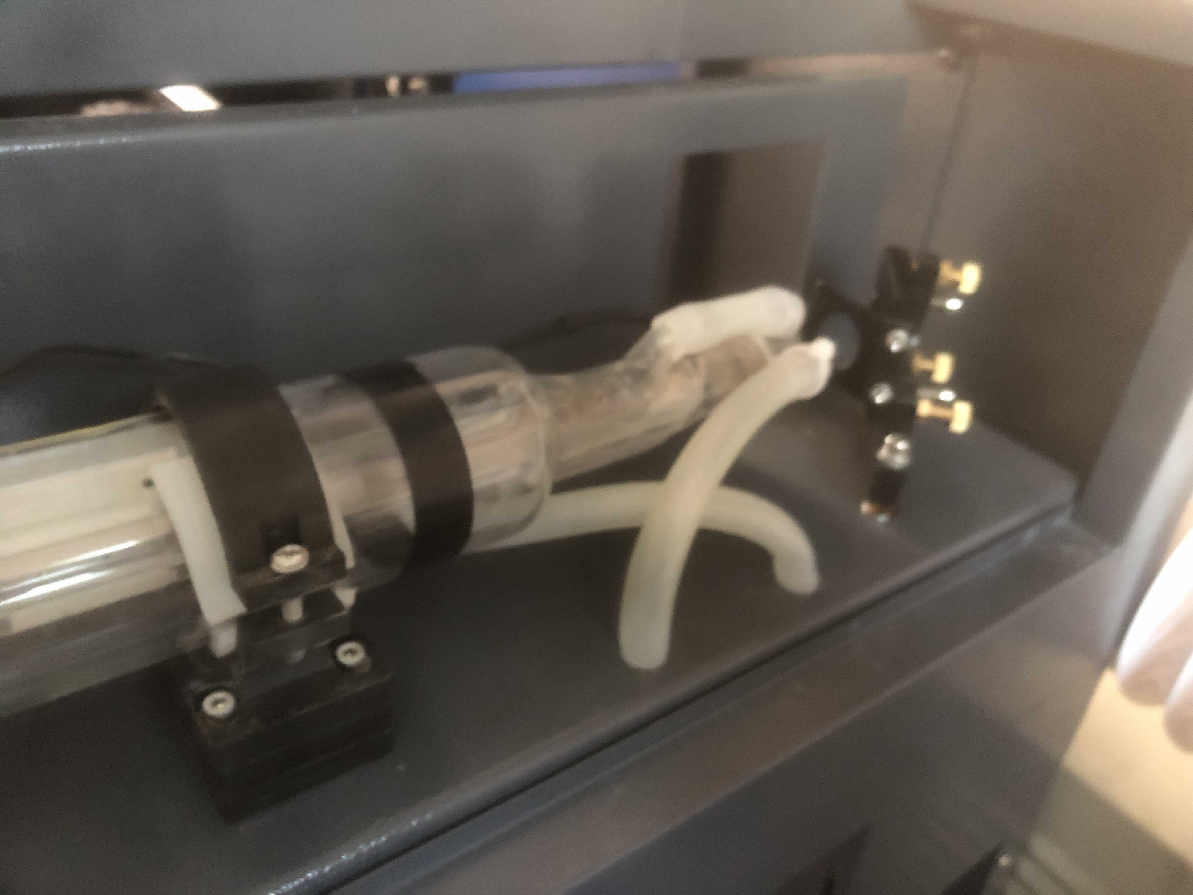
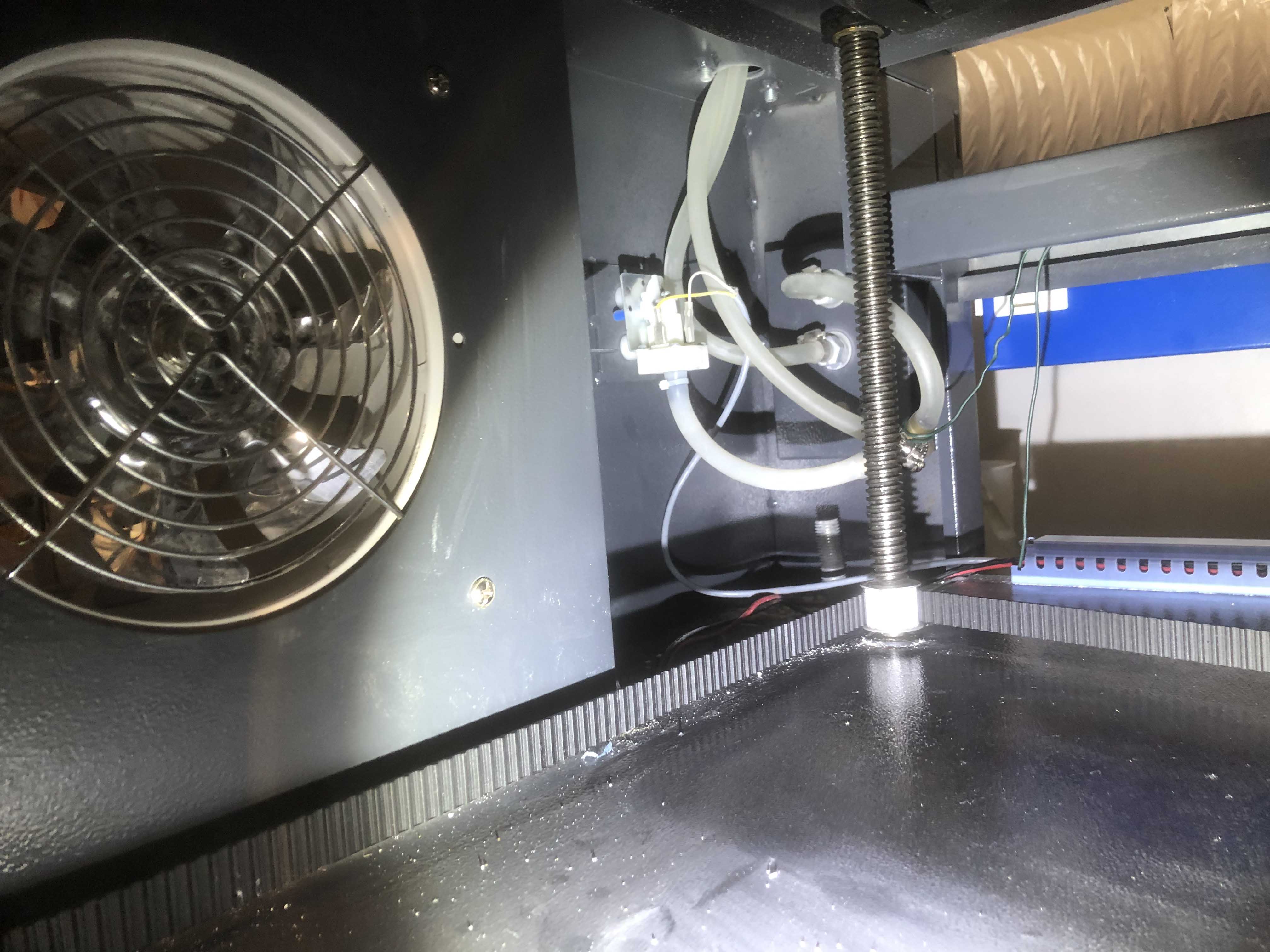
On your 2nd photo the 2 silicone hoses go down 2 holes into the super-structure of your machine. What happens to them in there? It’s one of those 2 hoses that will have the flow sensor if you have one.
I strongly suspect that either your chiller doesn’t pump water very well or you have the water trying to flow the wrong way through the system. Running/firing the tube without flowing water can damage it.
Thanks again for your reply. Not had chance to check anything out properly yet and apologies for the quality of photos, unfortunately the phone isn’t what it used to be.
The silicon tubes you mentioned I have followed around and this new picture attached is the only thing there although doesn’t look like a flow sensor. You have a tube going into it but with no return and looks difficult to get to if I need to.
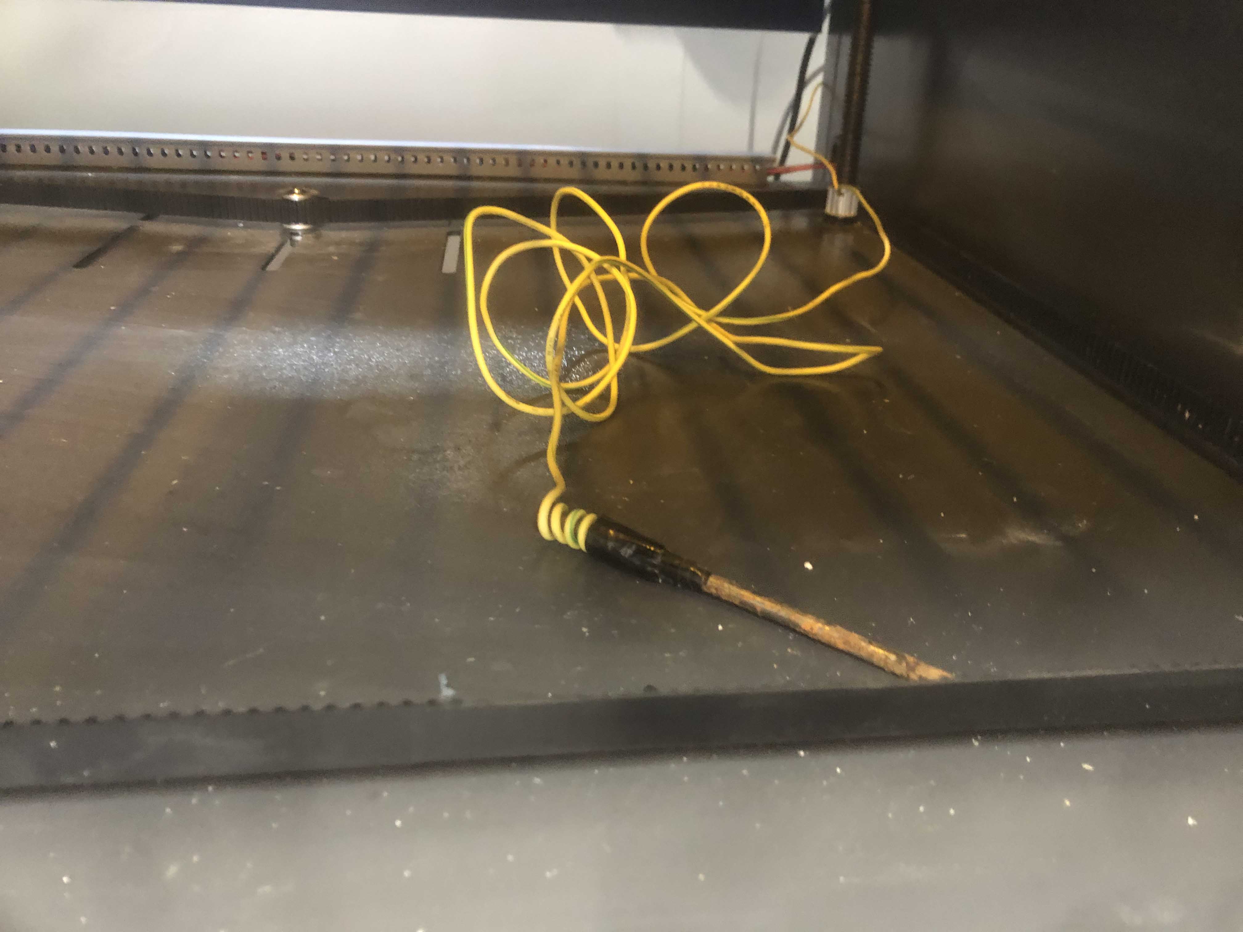
I also noticed coiled up an earth cable wrapped around a nail. Guessing this is the earth point and all this is ground as it should be. I specifically asked about this and was told it was all good as clearly I didn’t want anything bad to happen.
Assuming the fix is a submersible pump and nothing else has been damaged can I put some sort of inline flow sensor that alarms to give me advance warning if something is not right? Thanks.
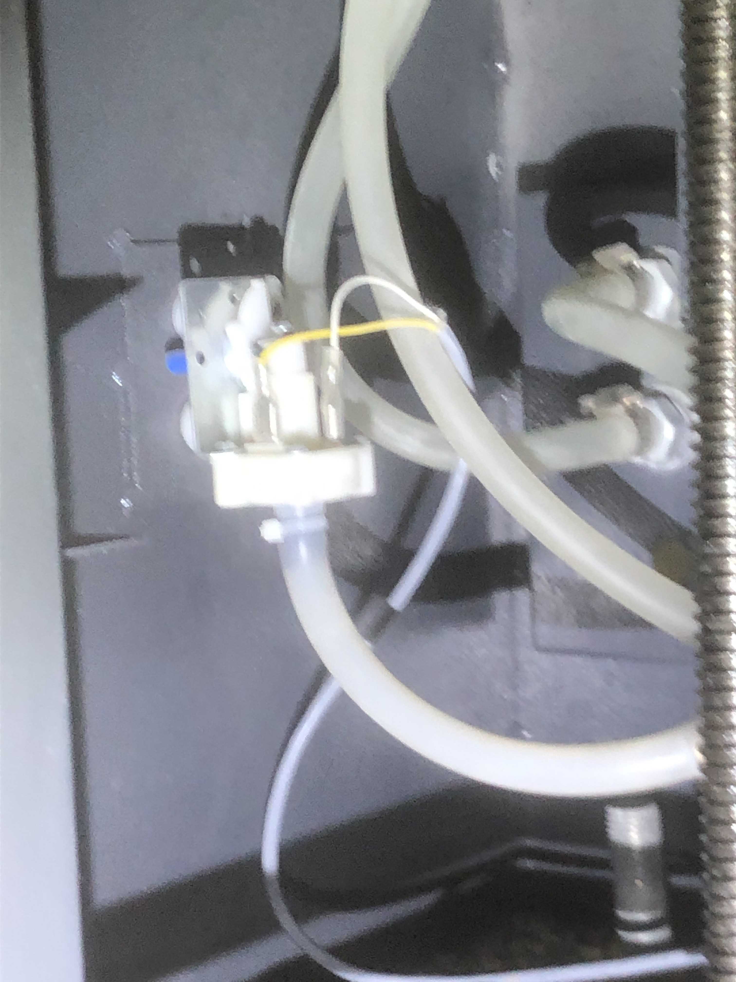
I’d like to see a much much clearer picture of this and also under stand what is going into it. It looks like some sort of flow sensor to me… if its not… then what is it for? The photo is just awful quality.
Told by and asked whom?  I suspect this was something that was in the Chinese instructions to do. We shouldn’t need to do this in the UK as our mains is (usually) properly earthed.
You need to know what all that plumbing does, where it goes, which way stuff is flowing through your tube… it might be “difficult to get to if I need to.” But its a lot easier for you to get at it than for anyone else.
So I thought I would just fire it up with my son and see how it was behaving. Bizarrely seemed alright I could see water circulating around the tube. We sent a test piece through and within a short period of time it was making a noise and I could see water droplets travelling down the high voltage connector, clearly not good. Switched it of.
I could see from the image attached although poor you can see a water droplet on the end of the tube and just happens to be a hole right underneath there where the water falls through towards the high voltage connector. When I squeeze the silicon tube water comes through but can’t work out if the laser tube is possibly cracked or the silicon tube maybe needs resitting. Either way even with the machine of very reluctant to mess at that end.
If you say I’m safe with everything of then tomorrow will see if I can resit the silicon tube but if laser tube damaged then of course that’s it I suppose.
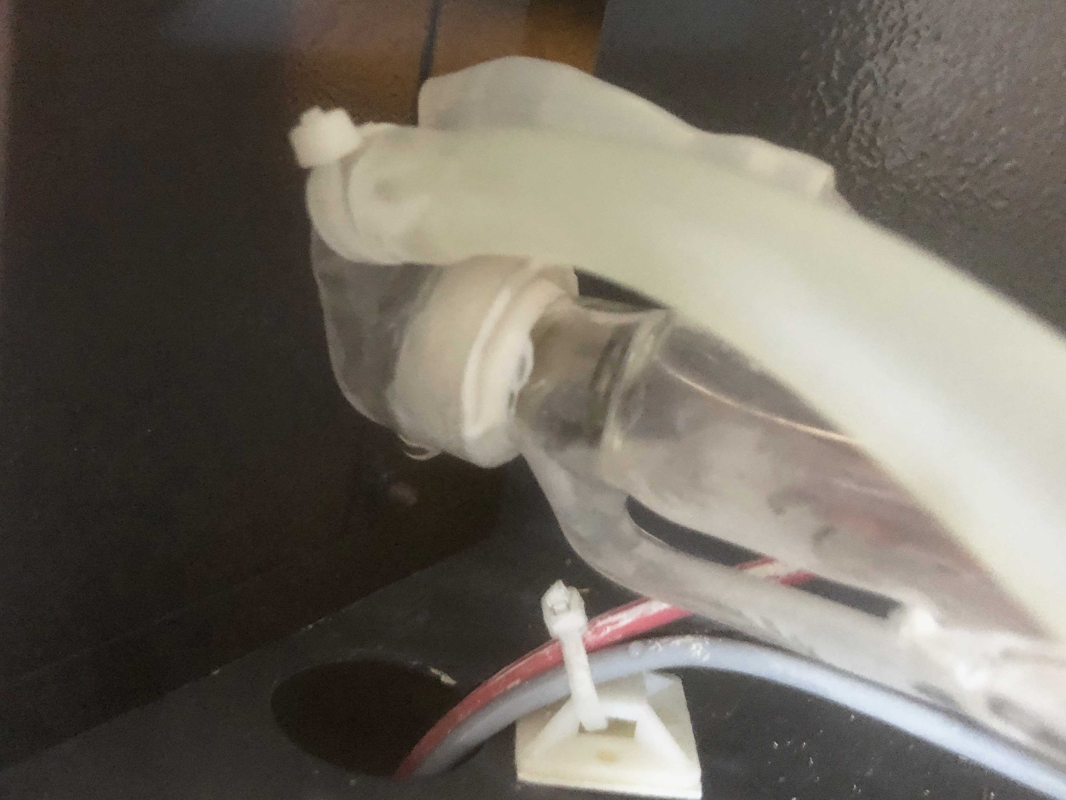
Thanks for the new pictures. I think this is a flow sensor, and it looks like it has a 3 way manifold connecting it to the inflow pipe (but its hard to say from the picture as its obscured).
As mentioned before you need to workout what all these silicone pipes are doing, where they’re going what direction water is flowing into them… a map of the whole hose system would be useful.
In the tube picture with the drip, you need to dry that off. I still can’t quite tell if the tube is correct, in the photo of the tube I could convince myself that there is water in parts of the tube that shouldn’t have water in, but that could just be the shadow and blurriness of your picture.
I suspect that you’re (inadvertently) pushing the water the wrong way through this system and its causing back pressure and no flow. That is the water can’t flow round and because it’s being pumped in its causing that drip, but again from the info you’ve given I can’t work it out.
At no point am I saying anything here is safe, whatever you do to your cutter is at your risk.
I of course took your advice and started to look at the flow lines of the silicon tubes, thought that would be easy but even that wasn’t straightforward. I was going to suggest maybe a bit of food dye in the chiller thinking this might show me direction of water etc.
Just before I planned to do that for no good reason I decided to swap the lines over on the laser, hey presto that seems to have sorted it out so it appears that possibly water was circulating the wrong way round.
I have yet to convince myself 100% that everything is as it should be but certainly the scary issues I had yesterday have gone. I will continue checking and keeping an eye on it was I always like to build up confidence with new hardware and software.
If this issue is resolved then a massive thank you to you for sticking it out with me to get to this stage as that doesn’t happen very often.
Is there a spec sheet out there for speed and power settings on a 60 watt tube that would save me a lot of time. I know it will only be a guideline but definitely a time saver. Thanks.
 that’s what I thought.
No. There are many more factors than the size of your tube. The quality of the tube, the optics, the alignment and that’s before mentioning that materials vary wildly in density, quality and moisture content.
However, I’d expect, at 65% power (you should not exceed that number) that it would cut through clear 3mm acrylic between 9mm/s and 20mm/s, 3mm Poplar plywood at around 25mm/s to 30mm/s, 3mm Birch at around 12mm/s - 20mm/s as some indicators… again, this comes down to a lot of factors beyond your tube.
Good luck.
Thanks never expected it to be an easy journey. That’s interesting as when I went to see it the chap cut some 10mm clear acrylic, wish I could remember what the settings were.
That’s interesting about the 65% power maximum. Is there a reason for that? Why can’t you go up to 80 or 90%? Assuming this is just for cutting.
Whilst engraving I was achieving what I thought were good results on some birch ply at 100mm x 20% power. Going to be a case of trial and error I suppose.
Hello again, my amateur research suggests you can change the focal point on the laser, so would I be better on the 41mm setting I have to do the engraving etc and depending on thickness change the lens to whatever you feel is best to get a one pass cut on for eg 6mm or even 10mm substrate or am I completely of track here? Thanks
If he was cutting 10mm acrylic he’ll have been going slowly probably about 5mm/s. Your top power should be usually 65% - 70% power and not exceed that. At the end of the day its your tube so you can do with it as you wish.
It’s a bit like forcing water down a pipe… there is only so much water you can push down a pipe, pushing it harder won’t make the pipe wider. You’ll find that putting more power into the tube about about 70% won’t result in more laser power, just a shorter life span on the tube and power supply.
Building up a good understanding of the speeds and powers needed for laser cutting is a big part of learning about your laser.
In future please open a new appropriately titled topic for a new question.
Apologies, will do and thanks again.